
Relay Wiring Diagram (4-Pin & 5-Pin Automotive Relay)

Relays play an important role in modern electrical systems. Simply put, a relay is an electromechanical switch that toggles between ON and OFF states using an electrical signal. They are widely used in various applications such as automobiles, home automation, power supplies, and more.
In automotive systems, understanding the relay wiring diagram is essential for anyone working on electrical repairs and maintenance. In this article, you’ll learn everything about the relay wiring diagram, as well as 4-pin and 5-pin automotive relays. So, let’s start!
Understanding Relay Wiring Diagrams is crucial for anyone who works with automotive electrical systems. They show how a relay controls high-current devices using low-voltage signals, allowing for efficient and safe operation. Knowing these diagrams helps you diagnose and repair electrical issues in vehicles.
Table of Contents
What Is a Relay?
A relay is an electrically operated switch. They commonly use an electromagnet (coil) to operate their internal mechanical switching mechanism (contacts). When a relay contact is open, this will switch power ON for a circuit when the coil is activated.

When a small control signal passes through the electromagnet‘s coil, it attracts the actuator, moving it from one contact (normally closed or NC) to another (normally open or NO). When the control signal is removed, the electromagnet deactivates, and the actuator returns to its original position.
Related Article: What Is the Blue Wire On a Ceiling Fan?
Where Relays Are Used?
Relays are incredibly useful because the switching part (actuator and contacts) is separated from the mechanism that activates the switch (coil and electromagnet). This separation allows a small control signal, such as one from a microcontroller, to operate a large current switch.
For example, a microcontroller can send a tiny signal to the relay’s coil to control a high-power AC appliance. This setup is common in various applications, including home automation and power management systems.
In automobiles, relays are very important due to the numerous high-current components like headlights, heaters, motors, and audio systems. By placing relays near these components, a small control signal from the car’s computer can manage them. This approach reduces the need for heavy-duty wiring, saving space and weight.
Here is a short overview where relays are used:
- Automotive Systems: Controlling high-power components like headlights, fuel pumps, and air conditioning systems.
- Home Automation: Managing appliances, lighting systems, and security systems.
- Industrial Equipment: Operating machinery, motors, and safety systems.
- Telecommunications: Switching circuits in telephone exchanges and data centers.
- Power Supplies: Protect circuits and provide load switching in power management systems.
- Test and Measurement Equipment: Controlling various testing instruments and measurement devices.
Here, you can see the application of relates in this YouTube video:
Basic Relay Terminology
Since relays are commonly used in cars, it’s important to understand their terminology. This guide focuses on automotive relays, though some terms apply to all relays, such as NO (Normally Open) and NC (Normally Closed) contacts.
A standard relay has five pins:
- Two Coil Pins
- COM (Common)
- Normally Open (NO)
- Normally Closed (NC)
The control signal is applied to the two coil pins, and it needs to be 12V for a 12V relay. The other three pins – COM, NO, and NC – make up the high-current switch.
The COM pin acts as one terminal of the switch and serves as the pivot for the actuator. It’s usually connected to the 12V power supply for the component, such as a light bulb.
The NC pin is connected to COM by default when there is no control signal. When a control signal is applied to the coil, the actuator shifts to the NO pin. Typically, the device controlled by the relay is connected to the NO pin, though this can vary based on the application.
Regarding automotive relays, the table below outlines the commonly used pin numbers.
| Pin Number | Description |
|---|---|
| 85 | Coil |
| 86 | Coil |
| 87 | Normally Open (NO) |
| 87a | Normally Closed (NC) |
| 30 | COM |
Related Article: What Is Relay and How It Works? Explained
Types of Automotive Relays
When it comes to automotive relays, there are 2 types that are used: 4-pin and 5-pin relays. Let’s take a look at each of them:
4-Pin Relays
The picture below shows a 4-pin Relay that is normally closed (NC). Here is an example of 4-pin Relay that is closed:

The picture below shows a 4-pin Relay that is normally open (NO). Here is an example of 4-pin Relay that is open:

5-Pin Relays
The main difference between these relays is that the 4-pin relay lacks the ’87a’ or Normally Closed (NC) pin, which is present in the 5-pin relay. Otherwise, they are quite similar.

Another key way to classify automotive relays is by the position of the COM pin. Based on the COM pin’s location, relays can be categorized into:
- Type A Relay
- Type B Relay
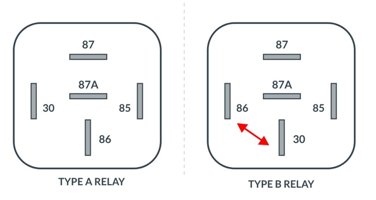
The image above illustrates the difference between Type A and Type B relays. It’s important to note that both types are available in 4-pin and 5-pin configurations.
Relay Wiring Diagram Explained
Having reviewed and explained the key terminology and pin configurations of relays, let’s examine some commonly used relay wiring diagrams.
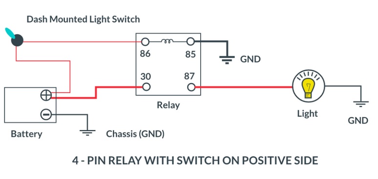
Make or Break Connection
The picture below shows a 4-pin relay with a switch on the Positive Side
The picture below shows a 4-pin relay with a switch on the Negative Side

Changeover Connection
The picture below shows a 5-pin relay that controls two different circuits.

Related Article: Which Is Better For PC: Shut Down or Sleep Mode?
FAQ: People Also Ask
How is a relay wired?
A relay is wired by connecting the control signal to the coil pins and the high-power circuit to the COM (common), NO (normally open), and NC (normally closed) pins. The control signal activates the coil, causing the actuator to switch between the NO and NC contacts, thus controlling the high-power circuit.
What is 85 and 86 on a relay?
Pins 85 and 86 on a relay are the coil pins. When a control signal is applied across these pins, it energizes the coil, which in turn activates the switch inside the relay.
Is a relay AC or DC?
Relays can be designed to operate with either AC or DC. The specific type of relay (AC or DC) depends on the application and the electrical system it is intended to control.
Final Thoughts
Relays are crucial in numerous electrical systems and essential in modern automotive technology. They enable the switching of high-power circuits using isolated low-power signals. However, relays can experience wear and tear due to their mechanical nature, necessitating replacement in vehicles like cars and bikes. Understanding relay pins, terminology, and wiring diagrams is invaluable for anyone working with relays, ensuring effective troubleshooting and maintenance.